Opacity Mask autogeneration for Normal map decals (Floating decals) in Unreal Engine 5
|
|
|
|
|
|
|
|
|
|
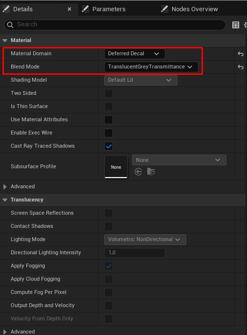
At the beginning, I would like to mention the material settings that are required for this setup to work correctly. Without changing these settings, the material created by default will affect all channels, including Base Color and Roughness, which is not needed for these decals.
|
Very often, surfaces on large or medium-sized objects in a game world are flat and need additional detail. Usually, decals are used for this purpose, so that real geometry does not have to be added and additional polygons are not wasted. However, decals usually look best when the geometry they contain has a rectangular shape. Otherwise, because the decal overlaps the underlying object, it requires:
The approach I decided to use as my base setup relies only on a Normal map usage and dynamically generates the Opacity map inside the decal material, based on the elements present in the Normal map. Of course, understanding how to create the node setup for this type of material is only one part of the process. It is also important to understand how the details should be prepared for baking the Normal map, since these details will later be used by the material to generate the opacity mask.
I am currently creating a spaceship bridge as a personal portfolio project, so I will take one part of it - a cabinet. At this stage, the geometric assets for my project are not finished yet, and the final materials have not been applied to the existing assets. So, for now, all attention is on the demonstration cabinet :) I apply a slightly unusual material to the cabinet - however, for demonstrating how the decal material I created works, it should be a very suitable example (to better see the difference).
|
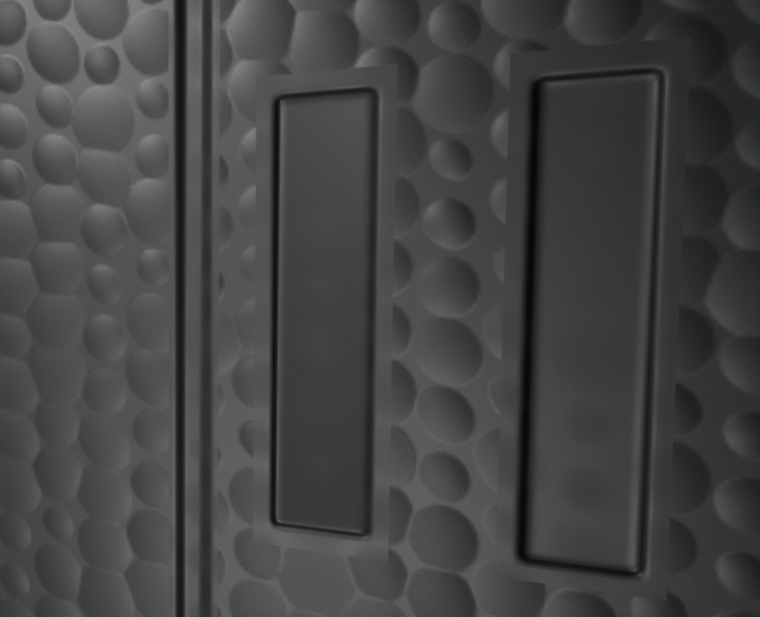
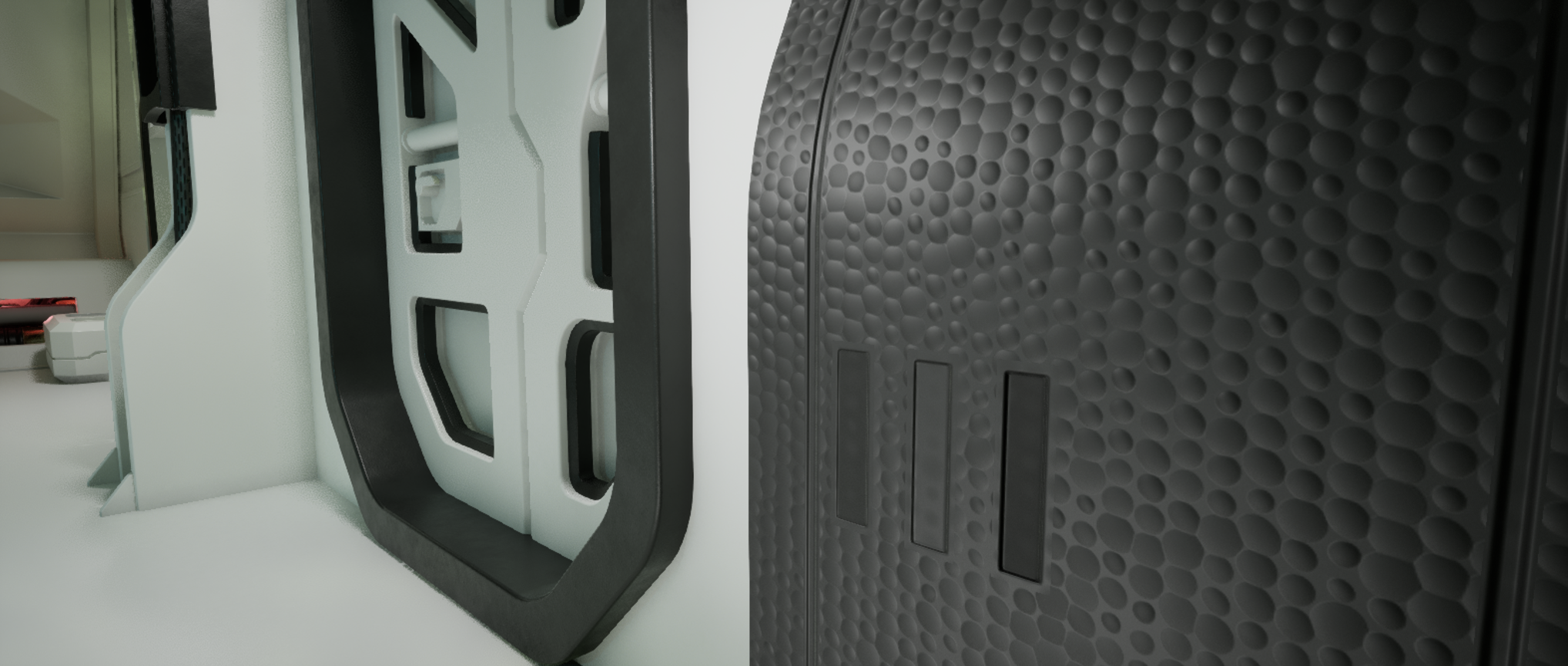
Below, you can see what the decals look like when rectangular UV shells are simply placed over a Normal map that contains the decal details. As shown in the screenshot, the area around the decal perimeter remains flat and overlaps the material of the main object, which is unacceptable from an artistic point of view.
|
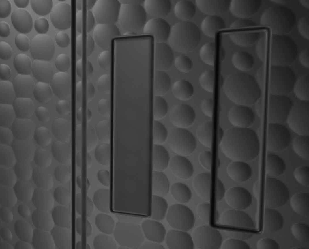
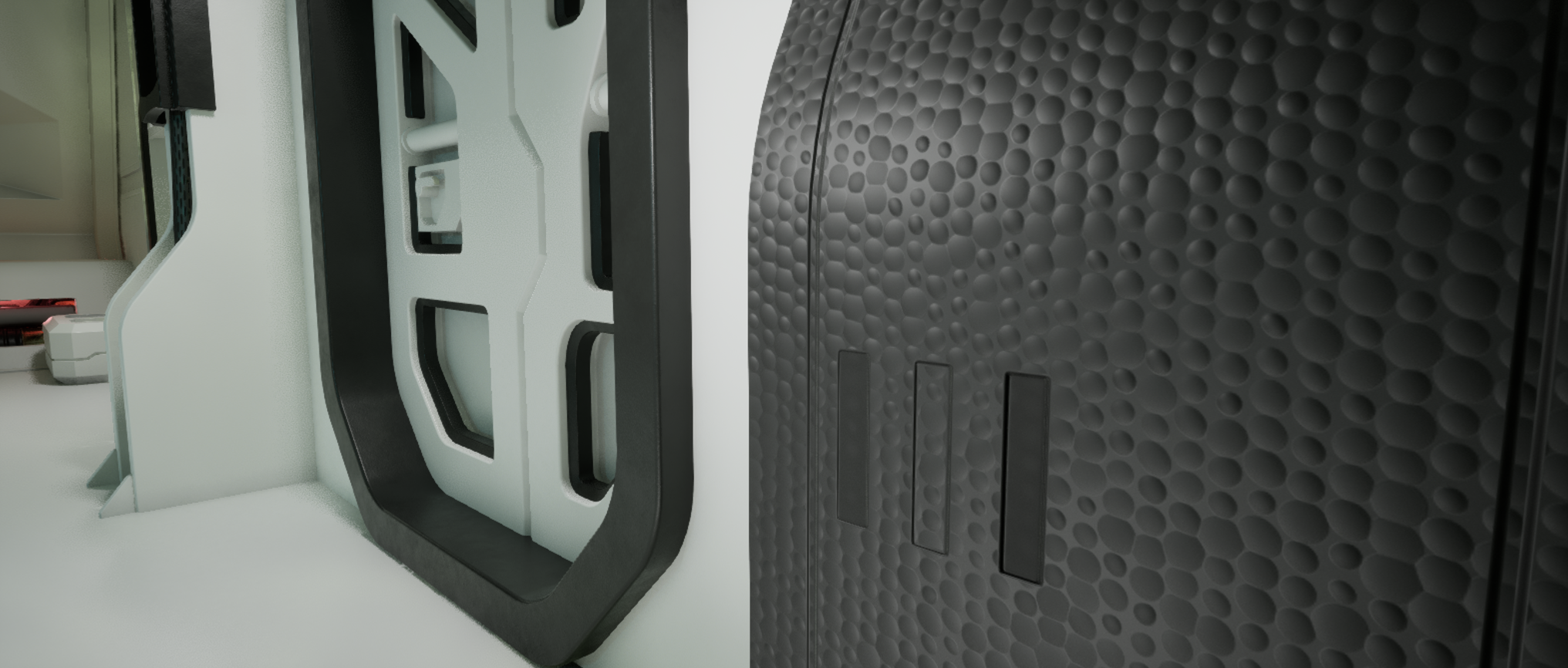
However, when I connect a chain of nodes to the Opacity Override socket, which generates the required grayscale mask from the Normal map, the decal details are applied in a way that does not break the visual integrity of the existing material on the main object.
|
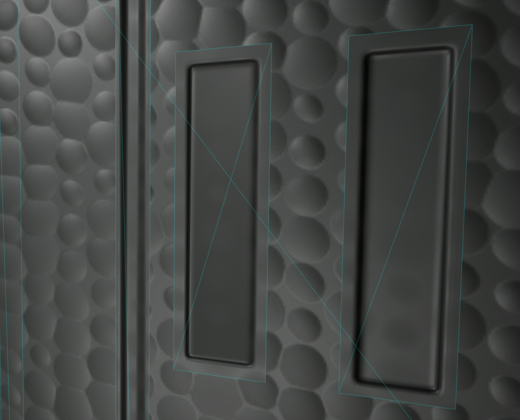
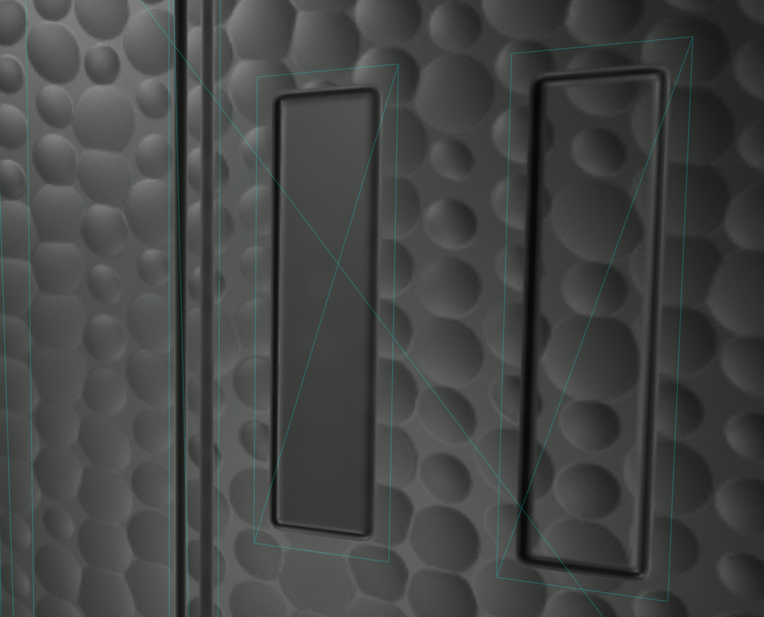
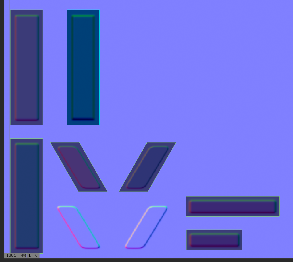
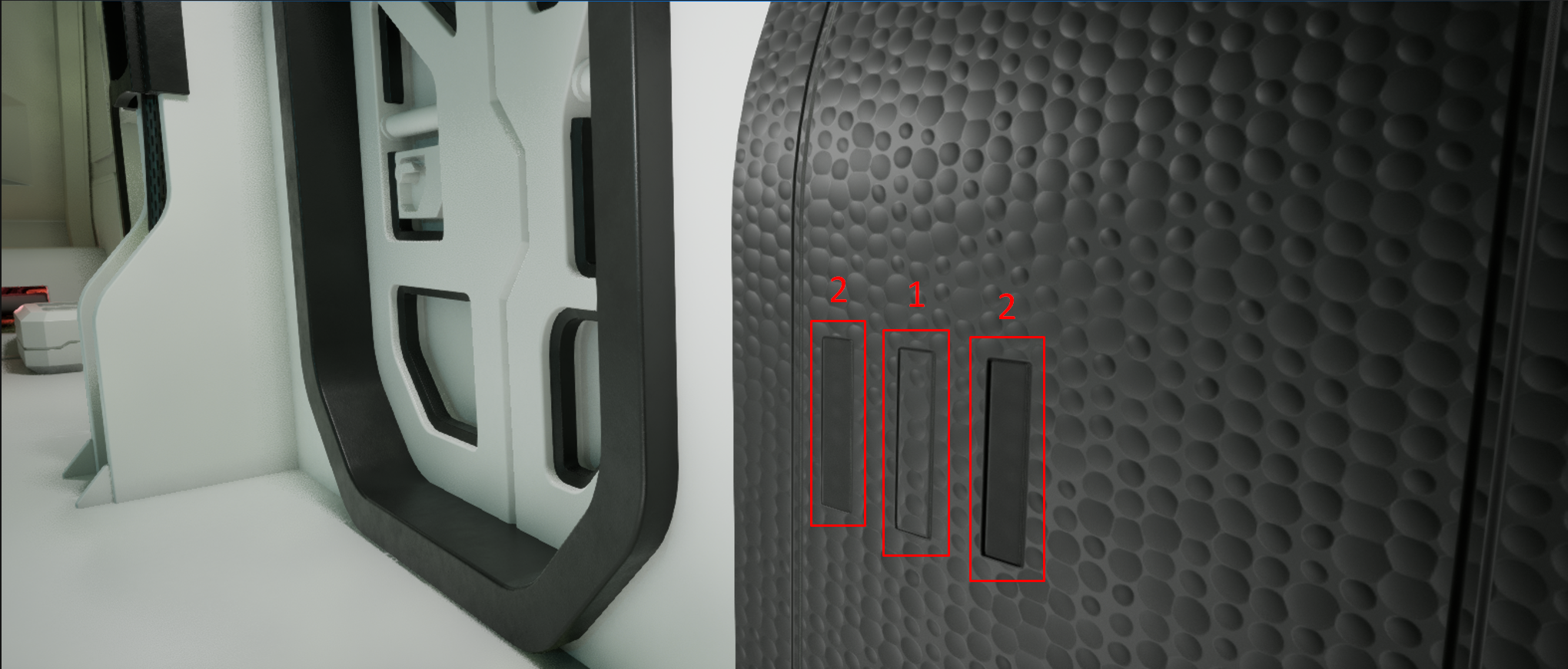
It is worth noting that, depending on the specific need, it is possible to create both decals that do not have a flat decal surface inside their perimeter (1), and decals that do have a flat internal surface (2), which replaces the Normal map of the underlying object.
|
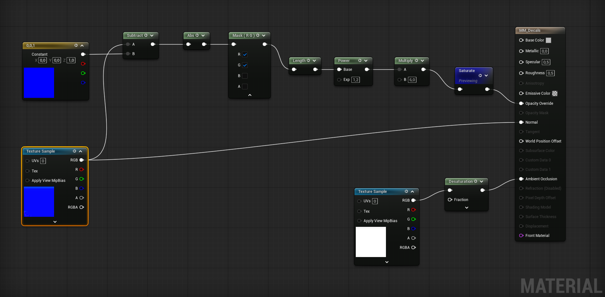
So, how do the nodes work in order to automatically convert the Normal map into a usable Opacity map? Below, I provide my material setup and explain how it works.
In my example, the Normal map and the Ambient Occlusion map are two separate files. I did this for clarity. However, for decals of this type, I would recommend packing the Red and Green channels of the Normal map into the Red and Green channels of the texture, and placing the Ambient Occlusion map into the Blue channel. Channel packing is a standard approach, including in workflows for Unreal Engine 5. It reduces both the number of assets inside Unreal Engine and the amount of memory they occupy.
|
In this guide, I do not cover the option of adding nodes that can be converted into Parameters and then used in a Material Instance to fine-tune each individual material that contains a decal atlas / trim sheet. This is a basic skill and is not part of this short guide. Here, I only want to explain my main idea and show how it can be implemented in practice.
To create an Opacity map from a Normal map, the main step is to separate the details that are actually visible and meaningful on the Normal map from the rest of the surface, which is not useful or needed. Since the useful information comes from the color transitions that store the direction of the normal vectors on the geometry, it is possible to separate this information from the unnecessary part: the flat surface, which has an RGB value of 128, 128, 255. Therefore, the first mathematical operation we perform is subtracting an “empty” normal map filled with RGB 128, 128, 255 from the added Normal map. This leaves us only with the geometry data that should be visible on the decal.
Constant3Vector / Subtract
To do this, it's necessary to add a Constant3Vector node and subtract it from the Texture Sample node that contains the Normal map, using a Subtract node. However, it is important to note that the Constant3Vector should be set to 0, 0, 1 - pure Blue - because there are two different representations of the same flat normal:
Here, Constant3Vector = 0, 0, 1 is not meant to represent the stored RGB color of the texture. Instead, it represents the decoded normal direction: a perfectly flat tangent-space normal pointing straight “out” from the surface. It is because Texture Sample node also contains already decoded Normal map.
Abs
After subtraction, some channel differences can become positive and some can become negative. But for the mask, we do not care whether the normal detail bends left or right, up or down. We only care: “Is this pixel different from the flat normal or not?”. So Abs turns all differences into positive “amount of difference” values. So we add Abs (Absolute Value) - it converts any negative value into a positive value, while leaving positive values unchanged. Without Abs, negative differences could cancel out or become ignored later in the mask calculation.
Mask (R G)
We use Mask node after Abs because, for opacity mask, we mainly care about the sideways deviation of the Normal map, not the blue/Z channel. And these are contained in Red and Blue channel.
Length
Length turns the two-channel R/G normal difference into one grayscale “strength” value that Opacity Override can use. After Mask R G, we have two values:
But Opacity Override needs one value:
So Length combines R and G into one number.
Multiply, Power and Saturate - The final touch
Because the raw Length result is usually not a good opacity mask by itself, it's worth using Multiply and Power after Length. Length gives the real strength of normal deviation, but that value is often too weak, too grey, or not contrasty enough for a decal opacity mask.
Multiply boosts the whole mask - it makes the mask stronger. When the normal-derived mask is too weak Multiply make the visible parts more opaque.
Power reshapes the grey values. Power changes the curve of the mask. It does not just make everything equally stronger. It changes how dark, mid-grey, and bright values behave.
Then Saturate clamps limits values above 1 back to 1.
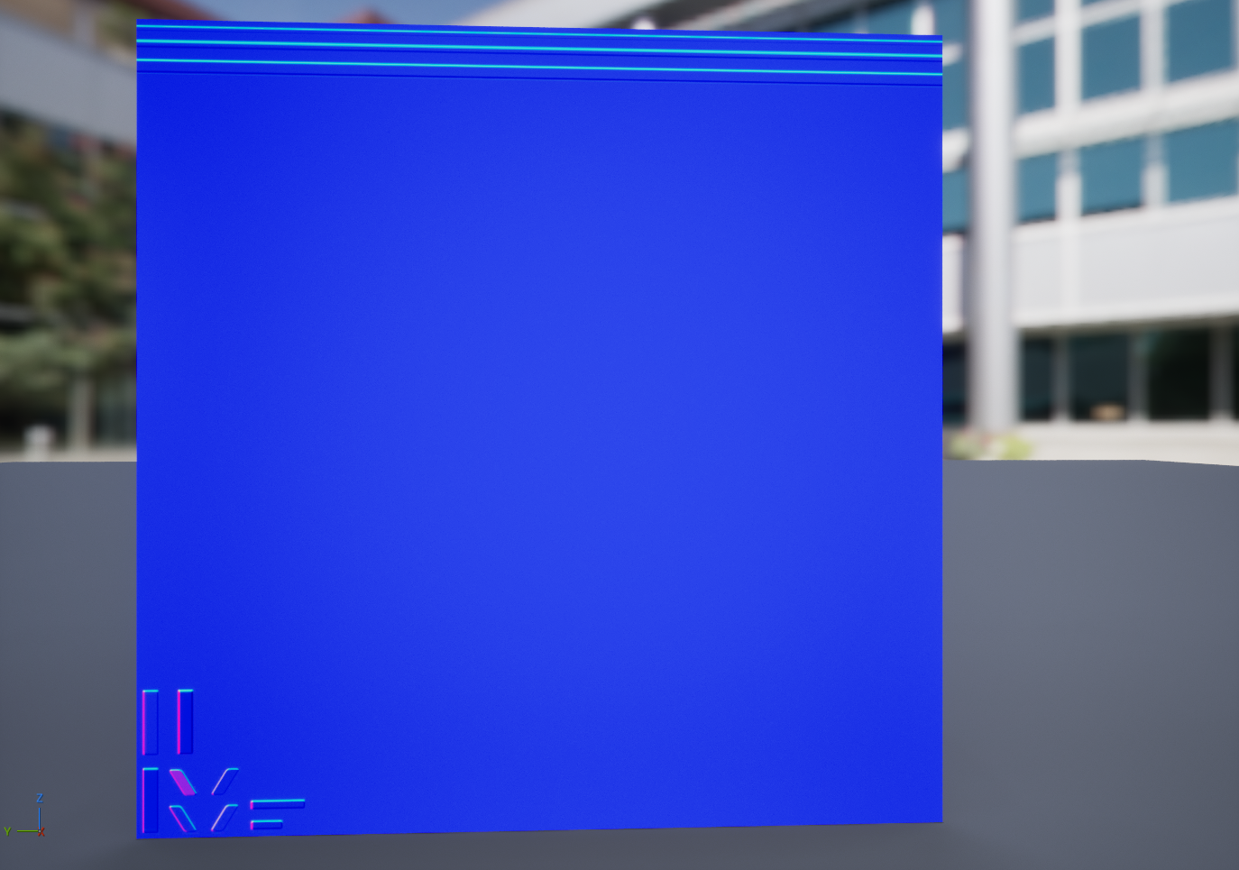
Decoded Normal Map |
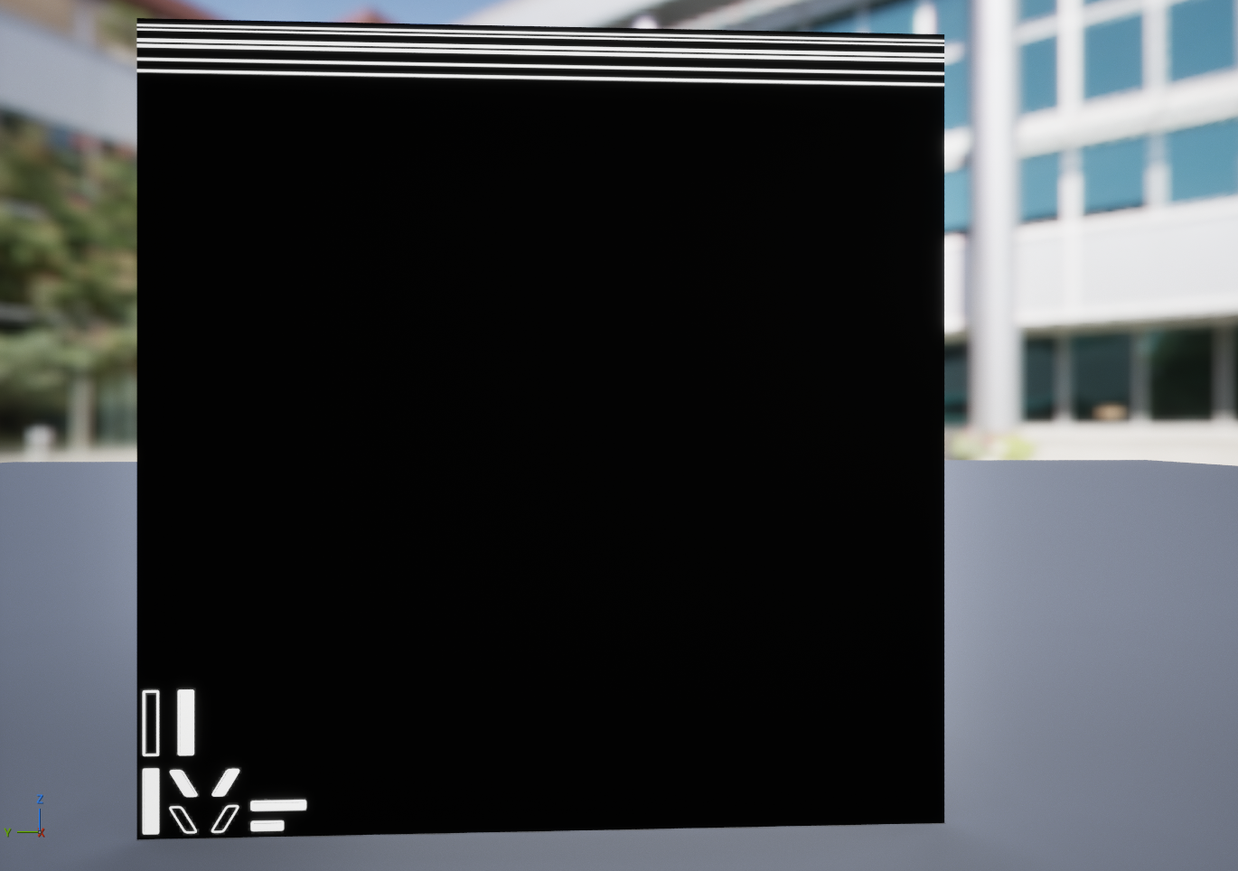
Opacity map generated from Normal map |
|
|
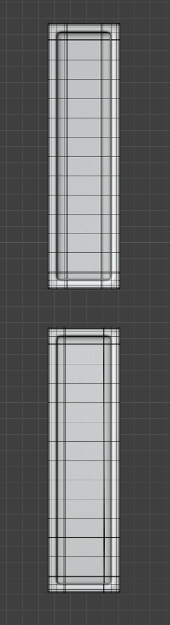
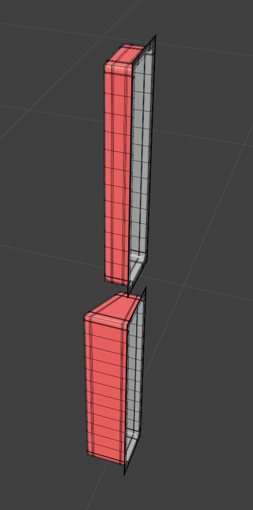
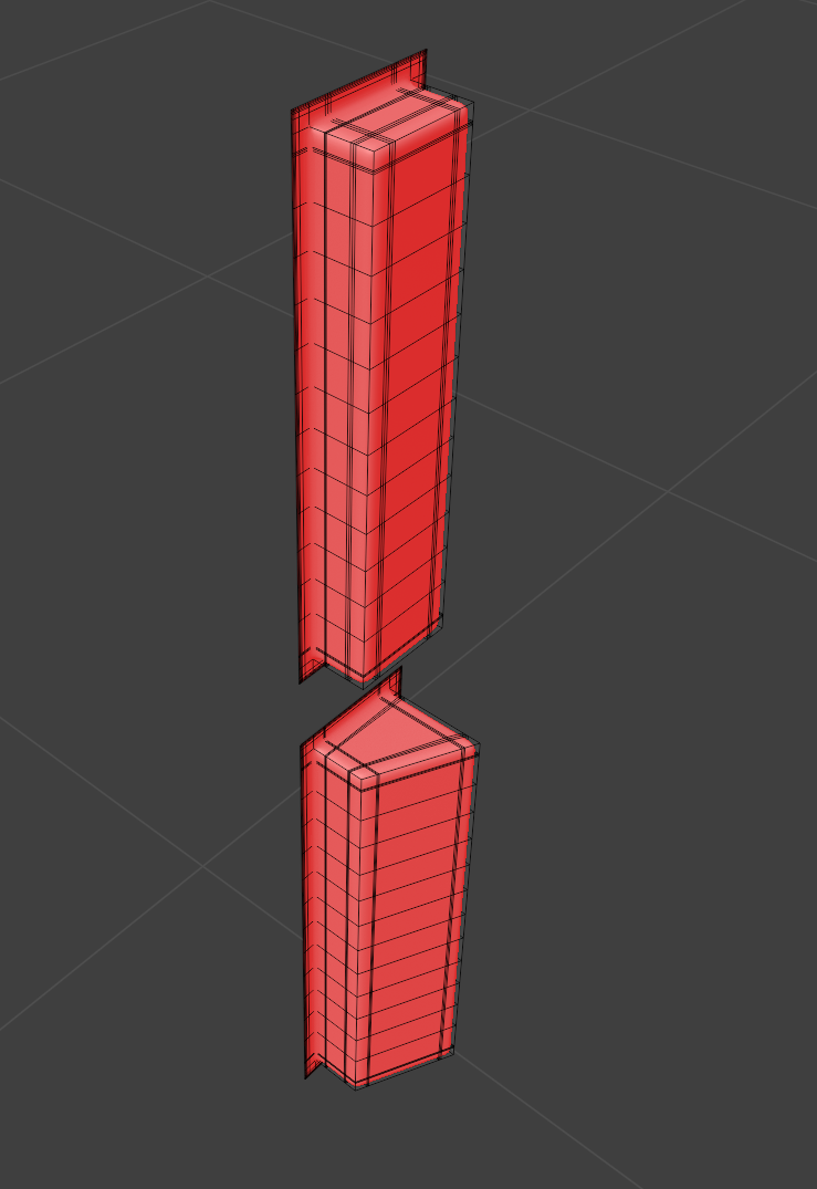
At this point, it probably becomes clearer how to make not only the decal perimeter visible, but also the internal area. To achieve this, the internal area must not be perfectly perpendicular to the decal surface. Below, I created two examples of geometry that look exactly the same from the front. However, when they are rotated, it becomes clear that one mesh has a back surface that is parallel to the baking surface, while the other mesh has a back surface that is slightly angled. As a result, in the first mesh (top one), the back surface will be represented on the Normal map as RGB 128, 128, 255 and will be excluded from visibility by the Opacity map. In the second mesh (bottom one), however, the back surface will be represented by a color gradient, so it will not be excluded from the Opacity map. This means that by making very simple adjustments to the geometry before baking the decal Normal map, it is possible to control which parts of the Normal map will be visible and which parts will not.
After that, the Normal map atlas can be modified without having to worry about whether the decal parts will be displayed correctly. Every time this texture is updated in Unreal Engine, the Opacity map is recalculated automatically, and you always get the Normal map visibility you need. The main requirement is that the surface between the Normal map elements remains flat.
|
|
|